
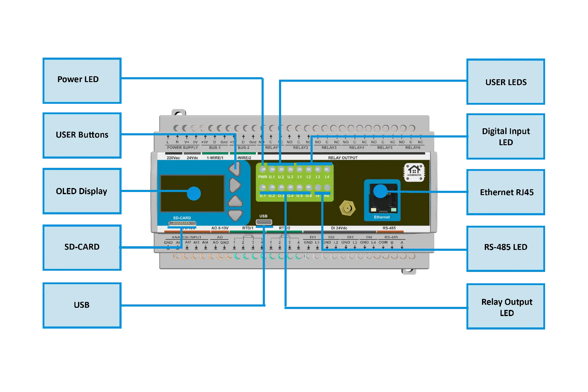
Power connection setup
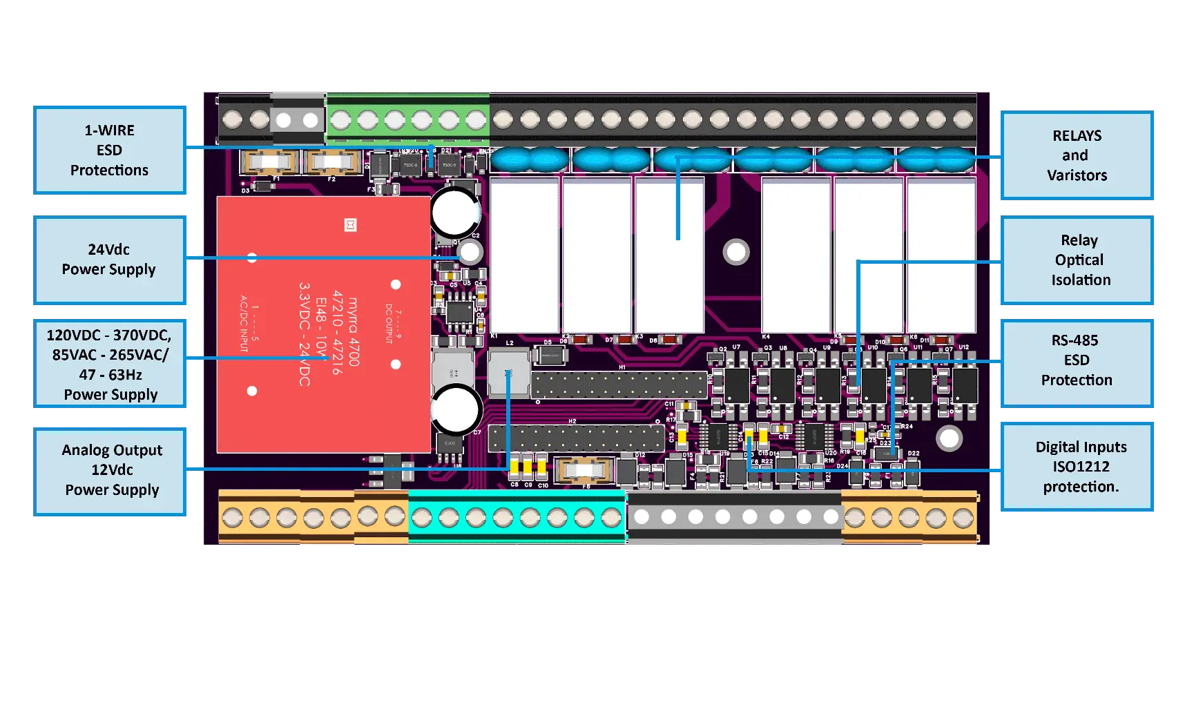
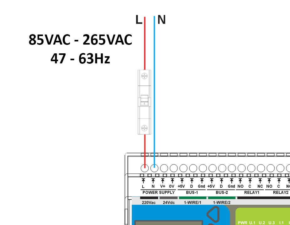
The MiniPLC can be powered either by an external 24VDC power supply or through its internal power supply. It is equipped with an integrated MYRRA 47156 power supply, which supports input voltages from 120VDC to 370VDC and 85VAC to 265VAC, operating at a frequency of 47 to 63Hz.
MYRRA 47156 specifications:
Output voltage (DC Volts) | Output current (DC mA) | Output Power (W) | Efficiency (%) | Ta (°C) |
24 | 220 | 5 | 79 | +50 |
The following is a simplified schematic of the internal power distribution:
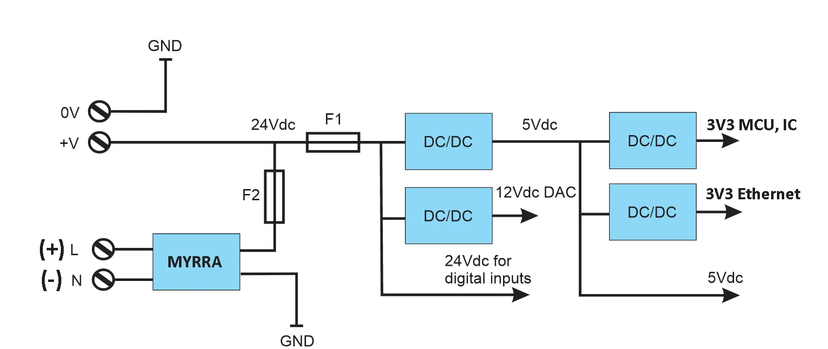
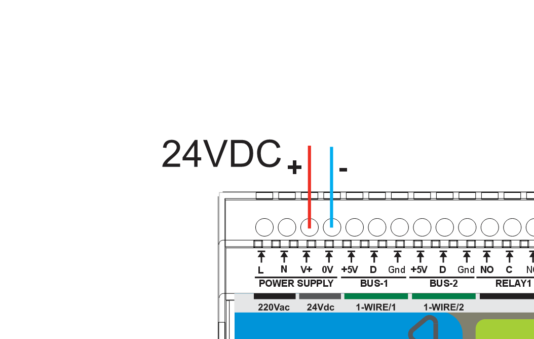
24VDC External power supply:
AC via internal power supply:
DC via internal power supply:
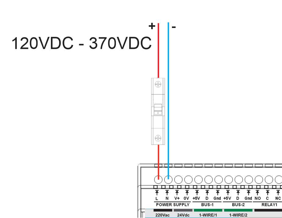
*Do not operate the internal power supply while a 24Vdc external power source is connected to the MiniPLC terminals V+ and 0V.
Connecting to the wireless network
To link the MiniPLC to your home Wi-Fi network, start by powering up the MiniPLC, and then use your mobile device or laptop:
1.
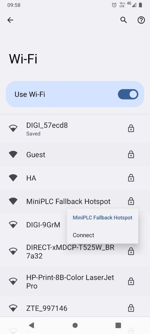 Connect to "MiniPLC Fallback Hotspot"
2.
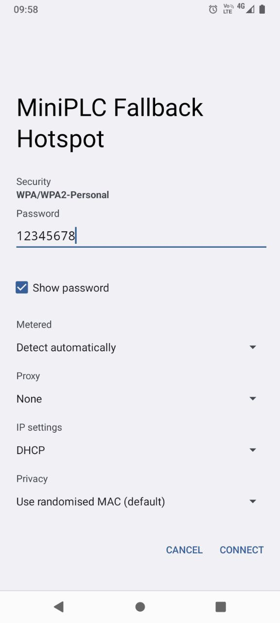
Log in using the password "12345678"
3.
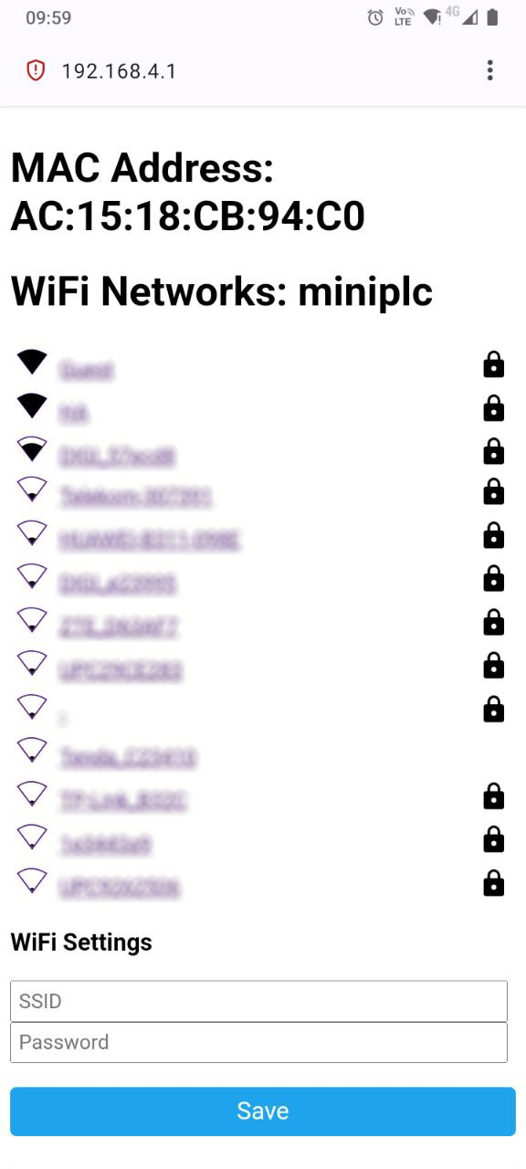
Access the URL http://192.168.4.1
Choose your home Wi-Fi network and input the password
4.
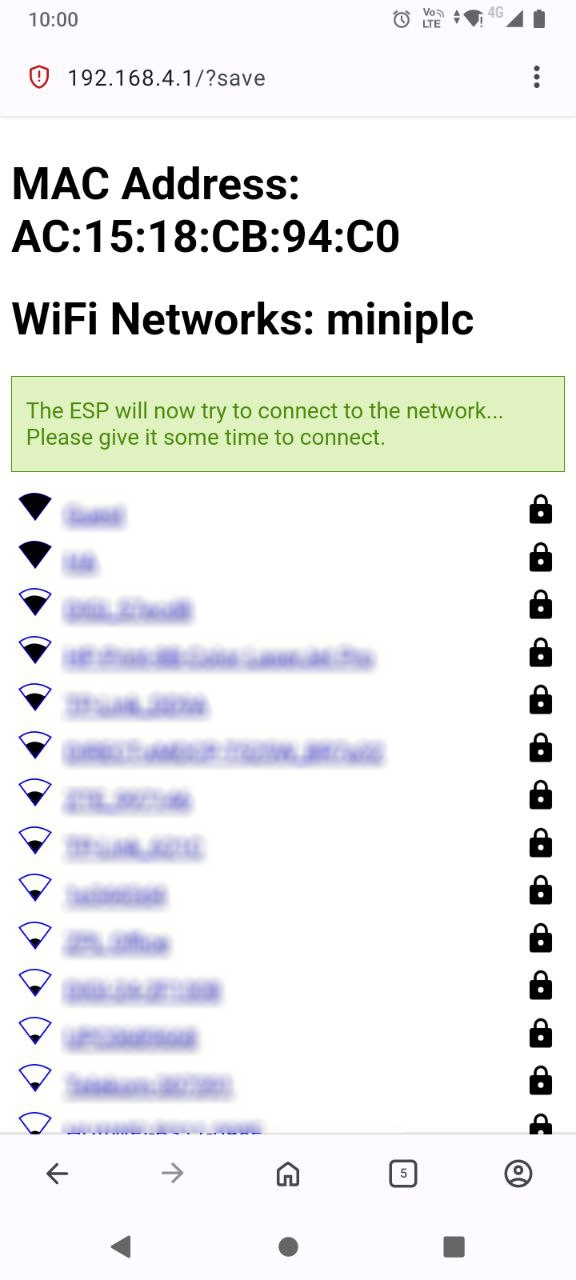
After pressing Save, you can view the assigned address of the MiniPLC in your router's interface.
Web Server
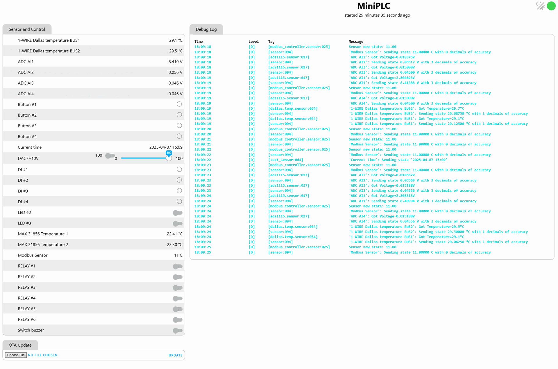
With the factory firmware settings, the MiniPLC includes a built-in web server. You can access it through your web browser by entering the address that your Wi-Fi router has assigned to the MiniPLC.
Build in webserver:
Connecting to the Home Assistant platform
Setting up ESPHome integration in Home Assistant:
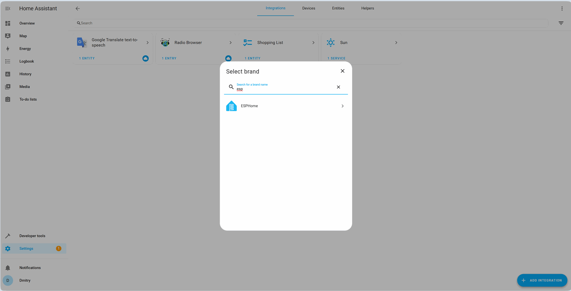
In the ESPHome integration press "Add device" and enter the address that your Wi-Fi router has assigned to the MiniPLC

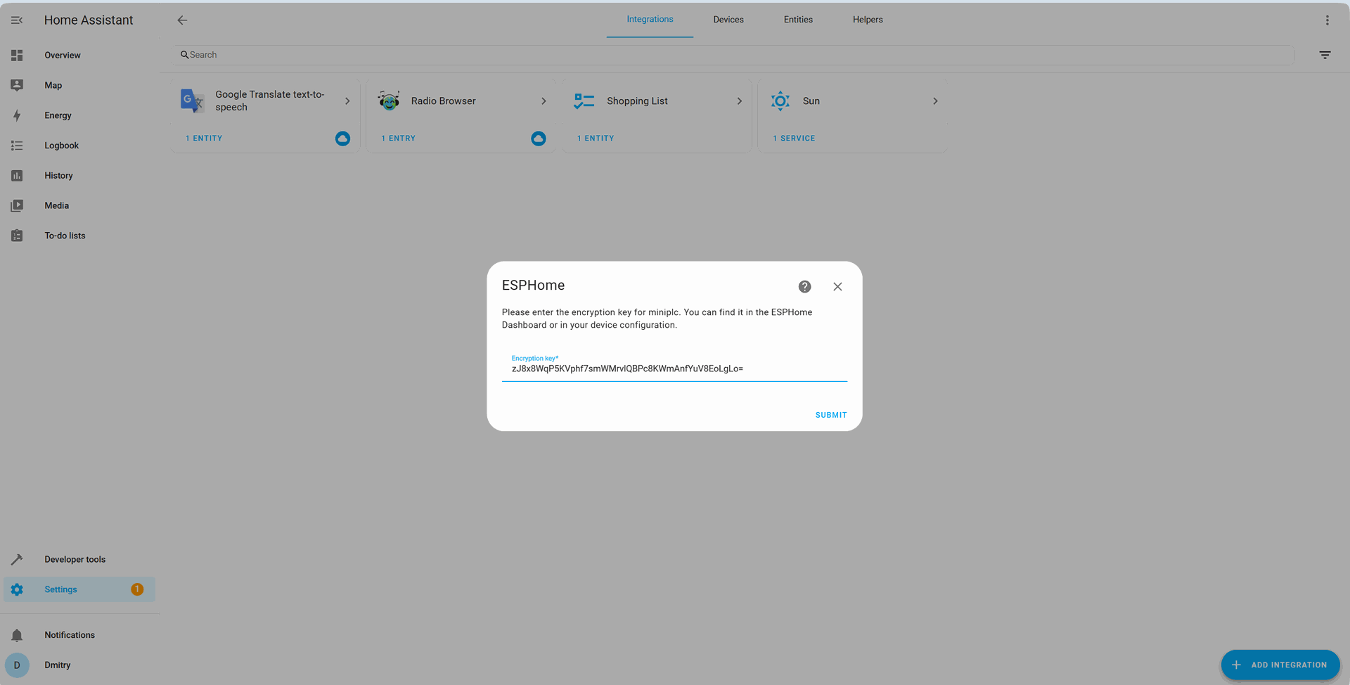
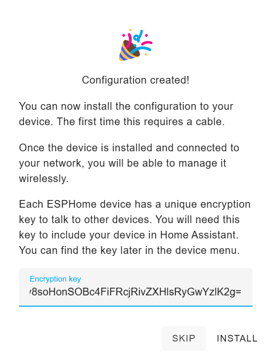
Input the encryption key from your configuration file, or the default encryption key provided in the factory setup firmware "zJ8x8WqP5KVphf7smWMrvlQBPc8KWmAnfYuV8EoLgLo=":
Upon successful addition of the device, the MiniPLC will be listed in your ESPHome integration:
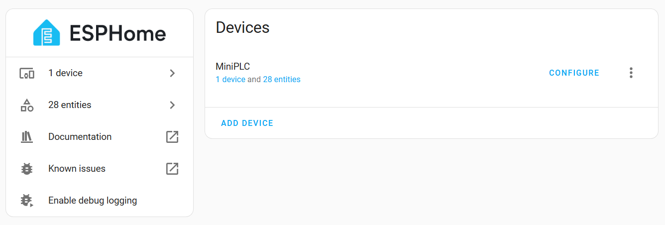
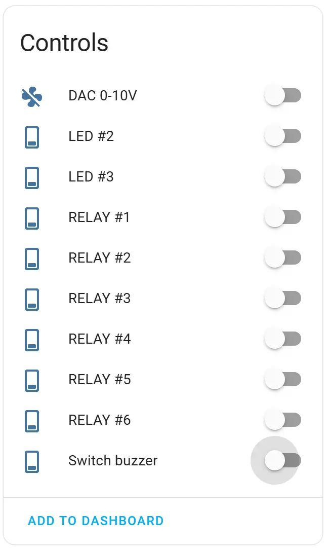
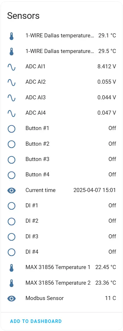
MiniPLC Controls and Sensors:
Firmware Download
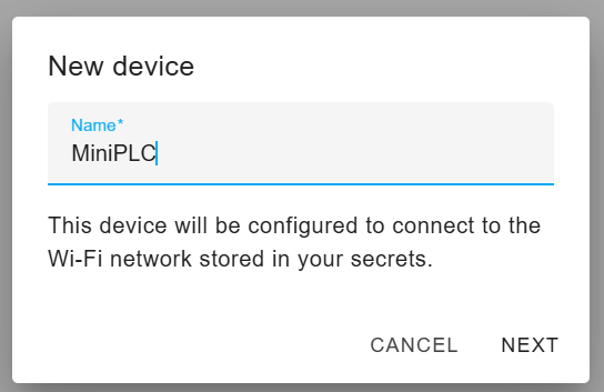
1. In the ESPHome dashboard add a New divece - "MiniPLC"
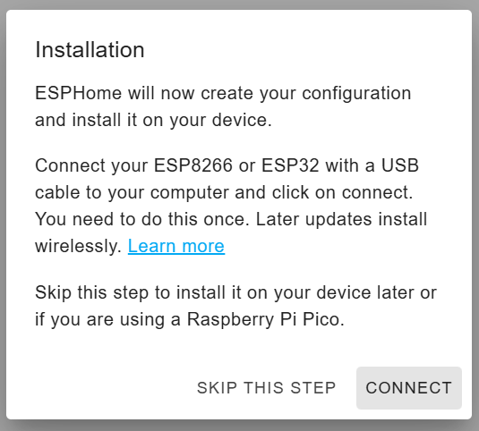
2. Skip the test:
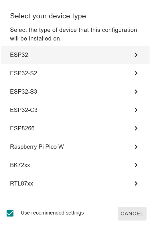
3. Select the device type - ESP32:
4. Choose skip installation:
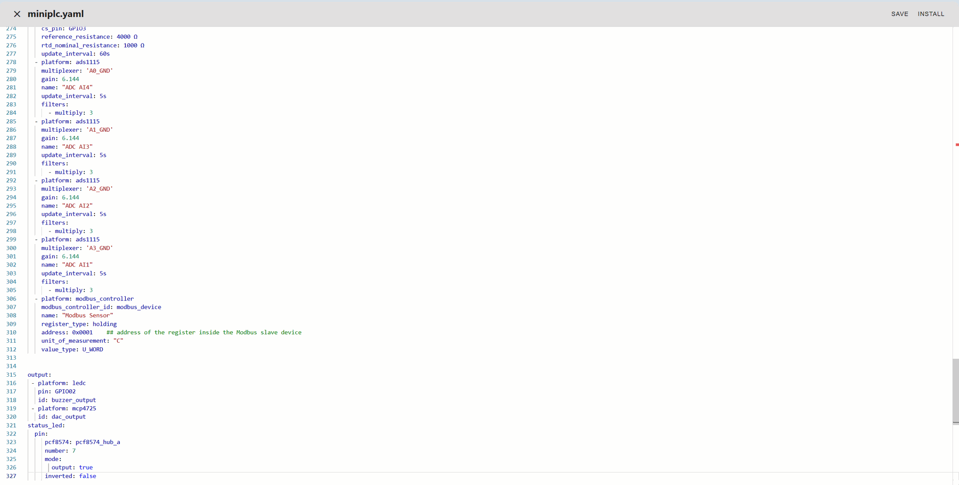
Modify the miniplc.yaml file according to your requirements (you can refer to the default yaml configuration file available on our GitHub page as a guide):
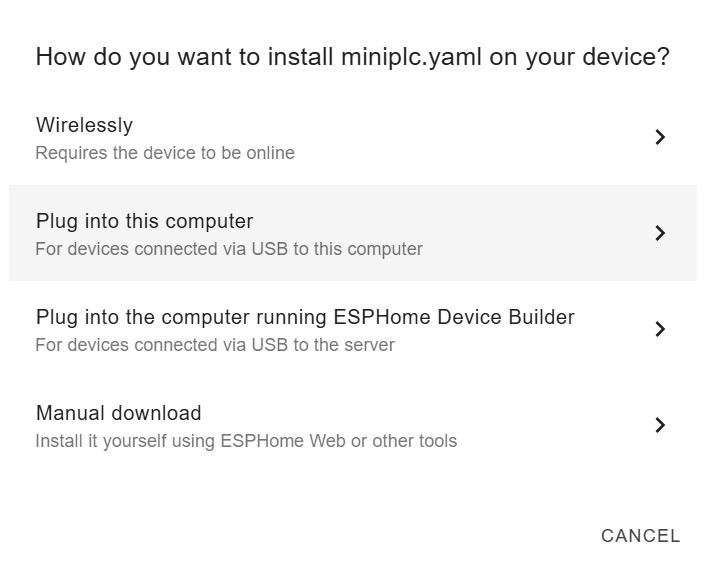
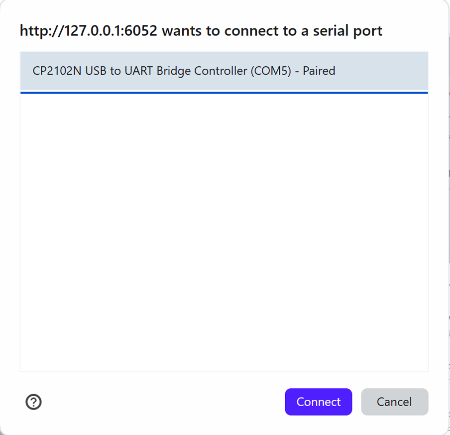
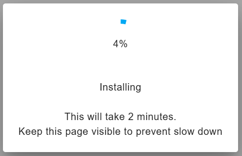
Install the settings through a Wi-Fi network, USB cable, or manually via OTA in the embedded web server:
Wiring diagrams :
1-WIRE
It is advisable to connect a maximum of 20 sensors to the 1-wire bus for optimal performance.
While it is technically feasible to connect up to 32 sensors, doing so will necessitate more complex wiring, which may result in reduced cable length and longer polling intervals.
For the signal lines DATA and GND, utilize a twisted pair from a shielded CAT5/6/7 cable. The VDD line can be connected to an additional conductor within the same cable.
Please ensure that the cable shield remains unconnected, and refrain from transmitting any other data signals through the same cable.
Connection Diagram:
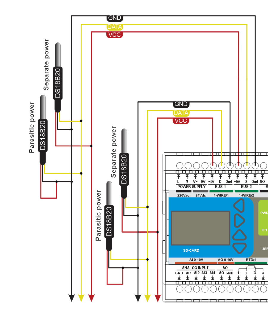
The maximum permissible length of a 1-wire bus is contingent upon the chosen wiring topology. In a linear configuration and a bus topology with short taps, the length can extend up to 300 meters. Conversely, for bus topologies featuring long taps and star configurations, the limit is reduced to 100 meters. When sensors are connected in a parasitic manner, the overall length must also not exceed 100 meters.
Numerous 1-wire sensors are designed to operate with parasitic power supply, allowing them to draw power through the data line (DATA) while the sensor's VDD is linked to GND. This configuration enables the elimination of one conductor, albeit at the cost of the maximum allowable length of the 1-wire bus.
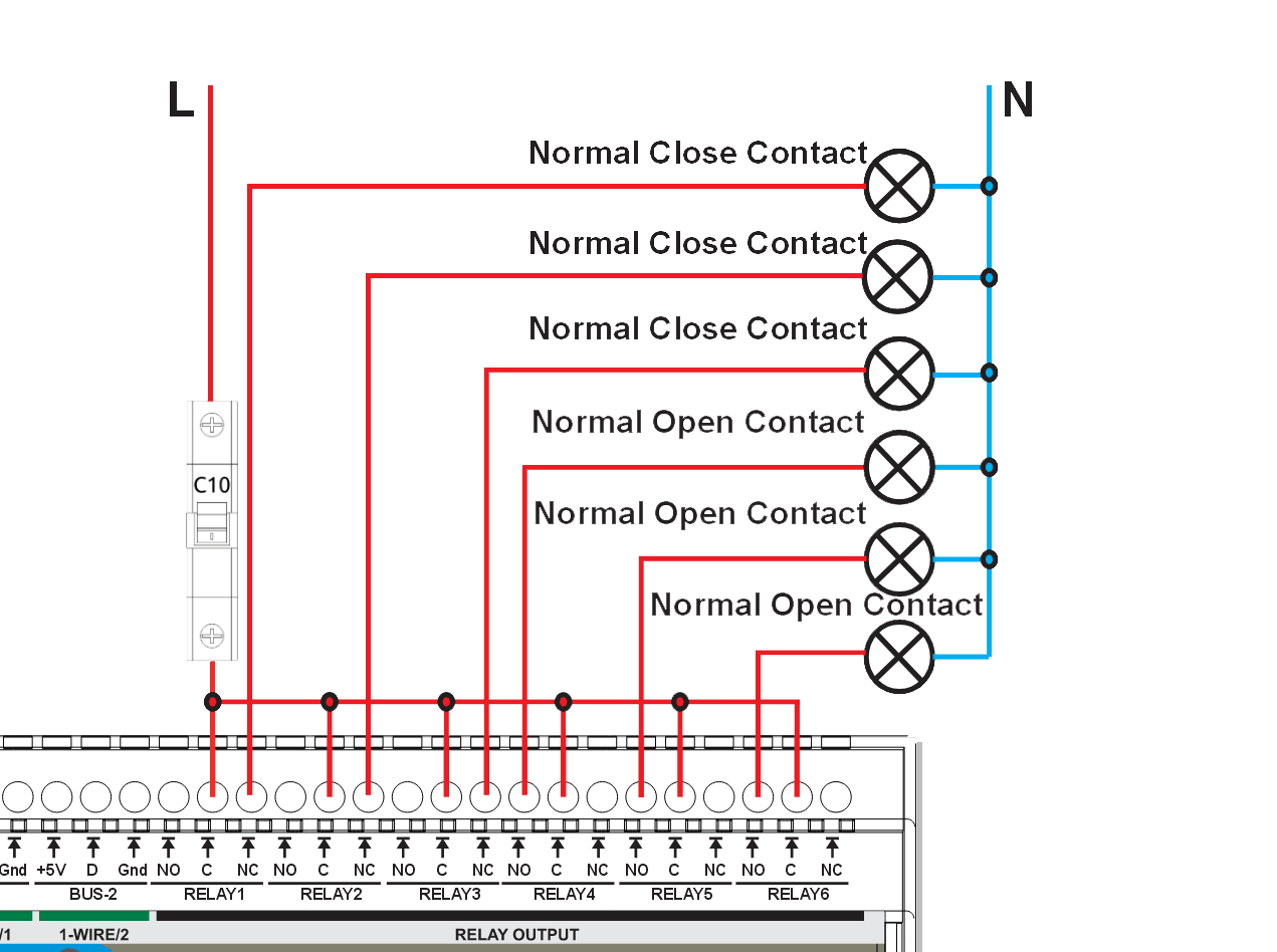
Relay Output
MiniPLC equipped with 6 digital outputs (incorporating relays with optocoupler and varistor for enhanced surge protection)
relays: Hongfa HF115F/005-1ZS3
dry contact specifications:
- 250VAC 16A at cosᵠ =1,
- 250VAC 9A at cosᵠ =0.4
- 30VDC 10A
Connection example:
Depending on the power and type of load, it is necessary to select a protective circuit breaker. At high power of consumers, it is necessary to install a separate protective circuit breaker on each relay. Or use a contactor.
Relay contacts inside MiniPLC:
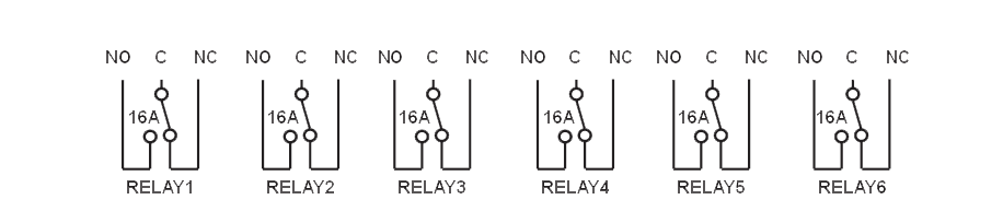
C* Each relay contact is protected from overvoltage by a varistor connected to contact "C”
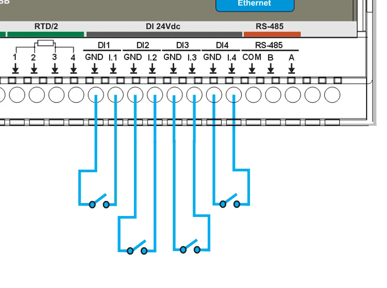
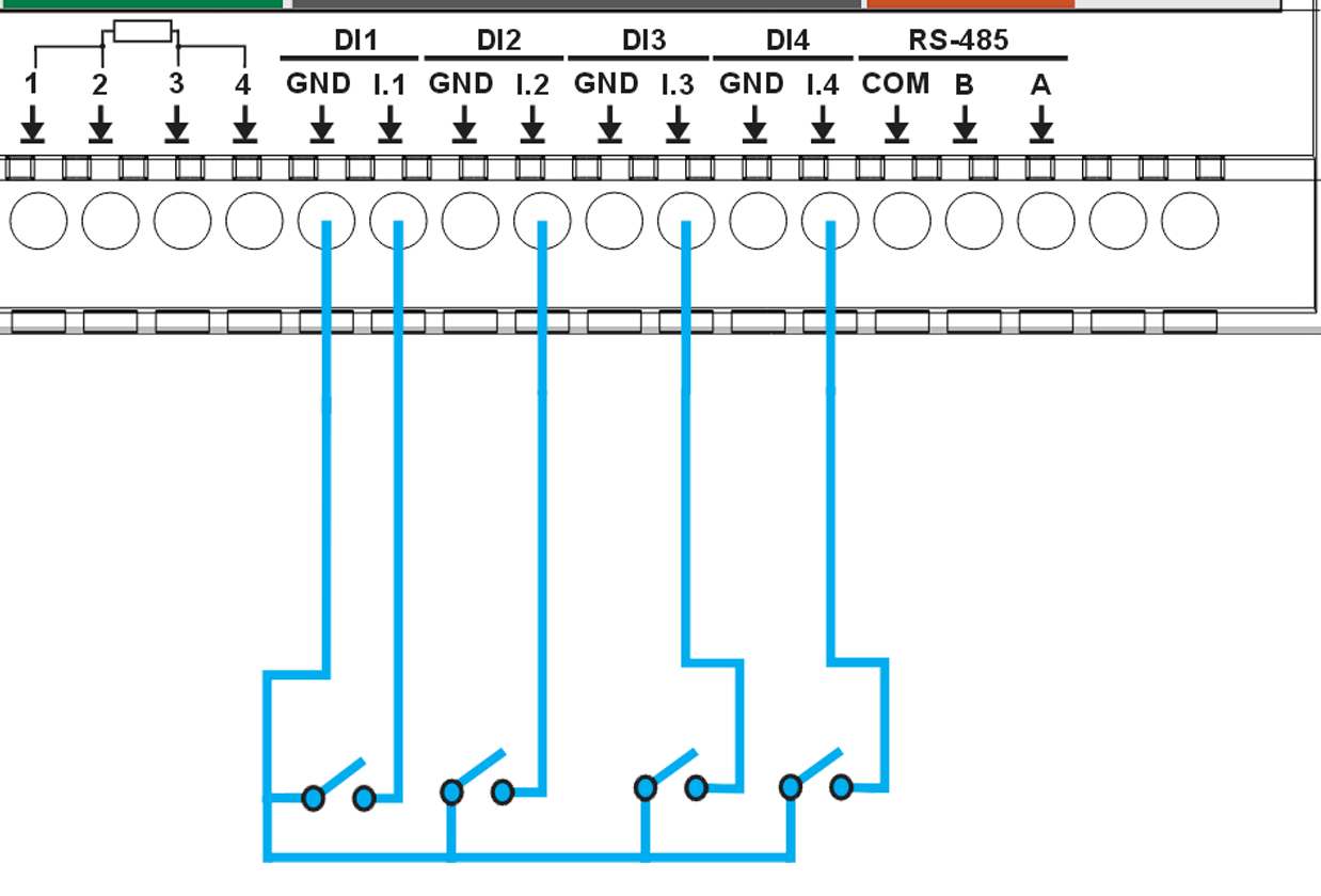
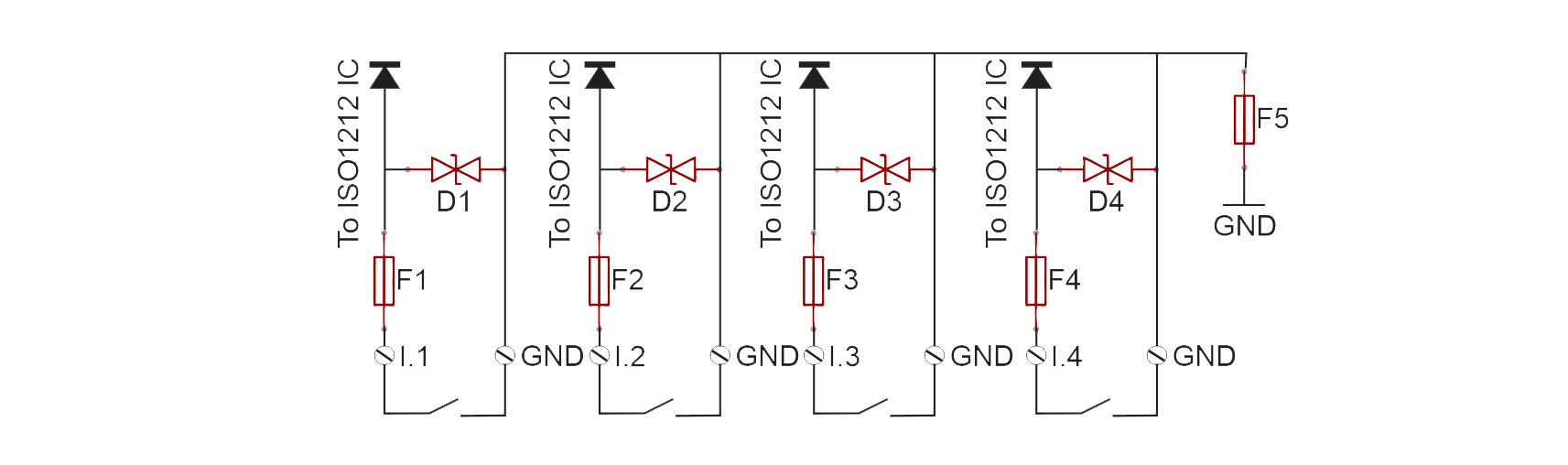
Digital Inputs
MiniPLC equipped with 4 isolated, surge protected digital sourcing inputs:
- logic 0: 0 ... 9.2VDC
- undefined: 9.2 ... 15.8VDC
- logic 1: 15.8 ... 24VDC
Connection example:
Digital inputs are designated as source inputs. It is important to note that digital input channels are not intended to serve as a power supply for any devices
It is possible to use individual GRDs for every input:
Also you can connect a common GND to any of the inputs:
Fuses and TVS diodes within the MicroPLC:
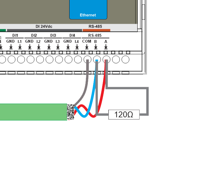
RS-485
In RS-485 communication systems, it is essential to utilize a shielded twisted pair cable to ensure optimal performance. A notable example of such a cable is the Belden 3105A, compliant with standards EN:50290-2-23 and IEC:60502. However, any cable exhibiting comparable specifications can effectively facilitate the interconnection of all devices within the network.
Connection example:
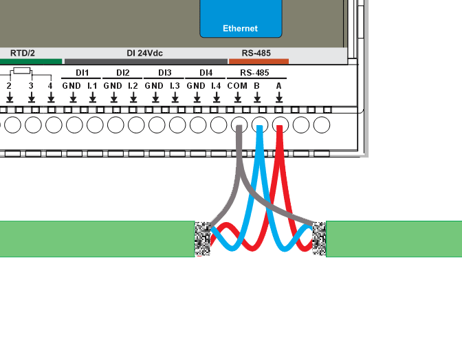
To avoid signal reflections, it is necessary to connect 120 Ohm termination resistors to the ends of the communication cable.:
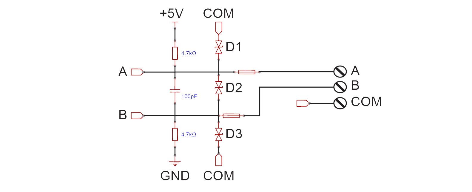
Automatic fuses and TVS diodes inside MiniPLC for protection:
RTD inputs
MiniPLC equipped with the MAX31865, capable of measuring 100Ω to 1kΩ Platinum RTDs (PT100 to PT1000) at 0°C. It supports 2-, 3-, and 4-wire sensor connections, features a 15-bit ADC resolution, and offers a nominal temperature resolution of 0.03125°C (which may vary due to RTD nonlinearity). The total accuracy under all operating conditions is a maximum of 0.5°C (0.05% of full scale). It includes fully differential VREF inputs, a maximum conversion time of 21ms, and ±45V input protection.
Additionally, it provides fault detection for open RTD elements, shorted RTDs, out-of-range voltage, or shorts across the RTD element.
Connection example:
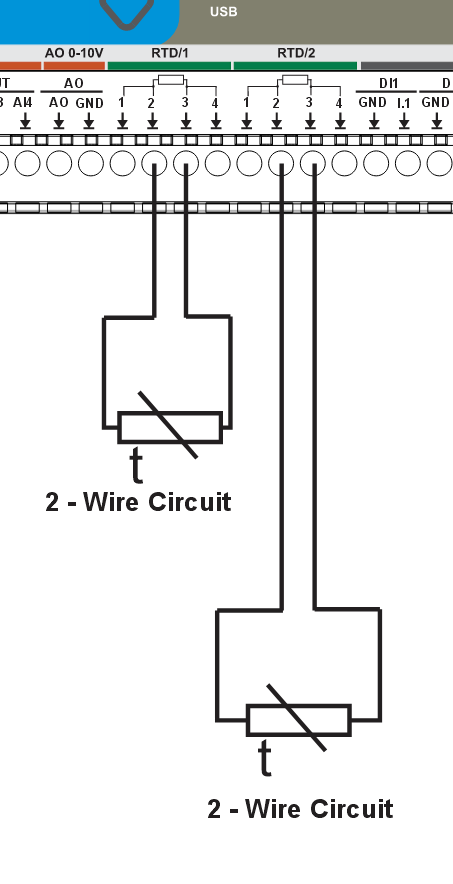
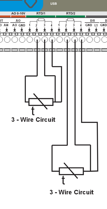
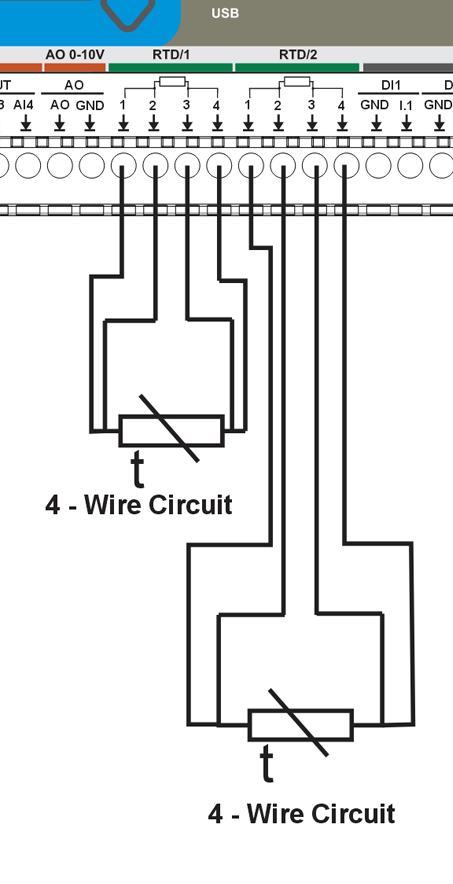
To configure the RTD for 2, 3, or 4 wire circuits with either PT100 or PT1000 types, it is essential to adjust the jumper settings on the MCU board:
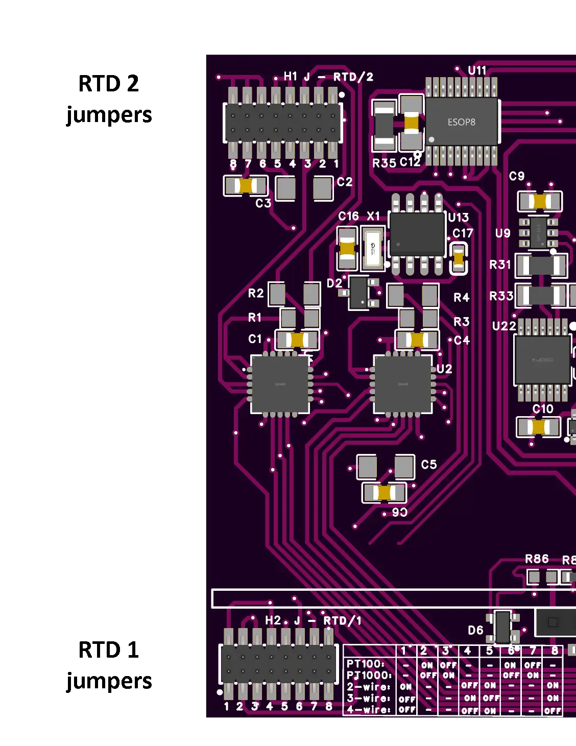
The factory's default jumper setup is configured for a 2-wire PT100 RTD type for the RTD/1 channel, and a 2-wire PT1000 RTD type for the RTD/2 channel:
J1 | J2 | J3 | J4 | J5 | J6 | J7 | J8 | |
PT100 | - | ON | OFF | - | - | ON | OFF | - |
PT1000 | - | OFF | ON | - | - | OFF | ON | - |
2-WIRE | ON | - | - | OFF | ON | - | - | ON |
3-WIRE | OFF | - | - | ON | OFF | - | - | ON |
4-WIRE | OFF | - | - | OFF | ON | - | - | OFF |
Additionally, it is essential to configure the reference resistor in the YAML file:
#MAX 31865 RTD
- platform: max31865
name: "MAX 31856 Temperature 1"
cs_pin: GPIO1
#Reference resistance for PT100
reference_resistance: 400 Ω
rtd_nominal_resistance: 100 Ω
update_interval: 60s
- platform: max31865
name: "MAX 31856 Temperature 2"
cs_pin: GPIO3
#Reference resistance for PT1000
reference_resistance: 4000 Ω
rtd_nominal_resistance: 1000 Ω
update_interval: 60s
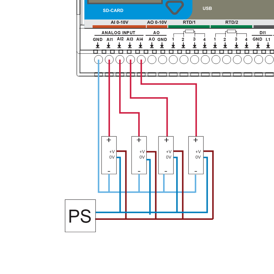
0-10V Analog inputs
MiniPLC integrated with the ADS1115, providing 4 analog inputs from 0 to 10VDC, featuring a 16-bit resolution through an operational amplifier, a maximum sampling rate of 0.86 ksps, ESD ratings of 2kV HBM and 1.5kV CDM, and includes EMI and RF filtering.
Connection example:
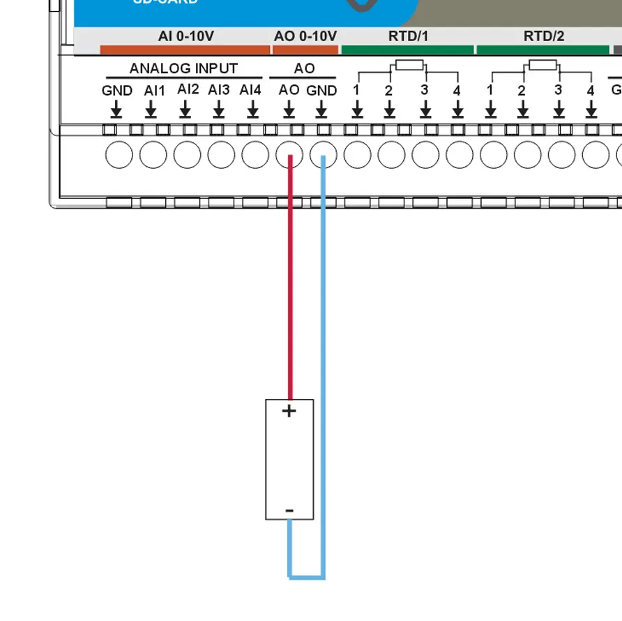
0-10V Analog output
A MiniPLC combined with the MCP4725, delivering an analog output range of 0 to 10VDC, with a resolution of 12 bits achieved through an operational amplifier.
Connection example: